10. December 2020
by M.-Leander Reimer | 1112 words | ~6 min read
smart office lorawan iot gcp serverless raspberry pi
The initial idea for this project dates back to November 2019, when I attended an event about the digital strategy of my home town Rosenheim. One of the talks at this event was about Rosenheim becoming a Smart city presented by speakers from Komro, the local internet provider, and the municipal utilities. They presented many ideas different use cases, like power cicuit monitoring or room climate control. See https://smartcity-rosenheim.de for more details.
Pretty much at the same time, we had just opened our QAware office in Rosenheim. It was apparant to me that the presented LoRaWAN technology together with a serverless backend would be an awesome combination to implement simple use cases such as CO2 monitoring in our meeting rooms or temparature readings in our server room. Unfortunately, COVID19 kicked in then and we had to transform our offices into safe environments to work. And guess what: even more use cases emerged like occupancy detection on shared desks and even toilets.
During our QAgarage day I finally found the time to write up this blog post and build the Klo Ampel, a digital occupancy indicator for toilets. Great fun!
The following is a shopping list of some of the hardware we used for this project. Of course there are many other LoRaWAN sensor devices you can buy.
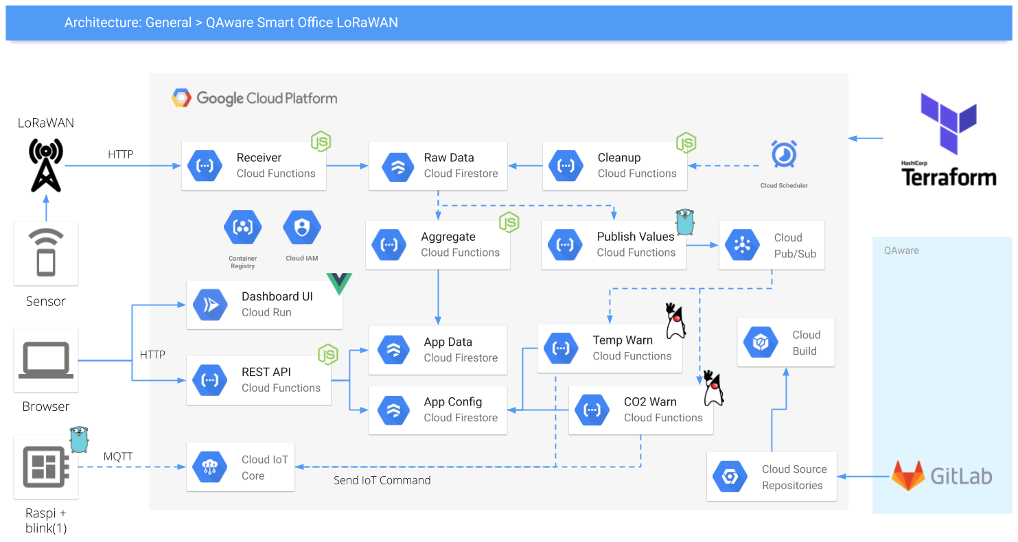
The general idea was to host the complete backend on Google Cloud and mainly use serverless technologies such as Cloud Functions, Cloud Firestore or Cloud Run. The basic infrastructure setup for the project is performed using Terraform, in order to create
The LoRaWAN devices are registered and connected to the local available LoRaWAN network. For our Rosenheim office we are using the network provided by Komro, and for our Munich office we use The Things Network with the HTTP integration configured. The sensor data is delivered to an HTTP receiver Cloud function, that decodes and stores the original payload as document in a Firestore collection. This function looks something like this:
| |
The whole backend logic is event driven and solely built using functions. Once the data has been persisted to Firestore, we use a series of Cloud functions to further process and aggregate the raw data. Some functions are trigger by the add and update events emitted by Firestore itself, others are trigger by Pub/Sub messages or cron jobs. As you can see from the conceptual architecture diagram we experimented with different runtime environments and languages. For simple functions it is really fast and convenient to write the function in plain JavaScript and use Node as runtime. However, using Go and Java for me felt very natural since these are my home turf.
We also built a small admin dashboard web UI using Vue. Nothing fancy, just a simple timeline view of the received data for each device and a device view with all current device readings. The UI itself is served from a containerized Nginx that is deployed on Cloud Run. The following code shows the cloudbuild.yaml used to build the Docker image using Kaniko and to deploy the image using the Google Cloud CLI.
| |
The data for the UI is exposed via a REST API implemented as a JavaScript function leveraging the Express.js framework. Each API endpoint is a simple function that queries Firestore and returns the result documents as JSON. I was impressed how quick and easy simple CRUD style APIs can be implemented this way.
| |
The final piece of the architecture is to connect further external devices to receive and act upon certain thresholds and events. For this we use the Cloud IoT Core and Pub/Sub APIs from GCP. Each client device (or application) is registered together with its public key at the device manager. The device later authenicates itself using a JSON Web Token (JWT) that is signed with its own matching private key. To communicated with the backend the client connects via the MQTT protocol to receive the commands from the backend. Have a look at the official Quickstart documentation for further details.
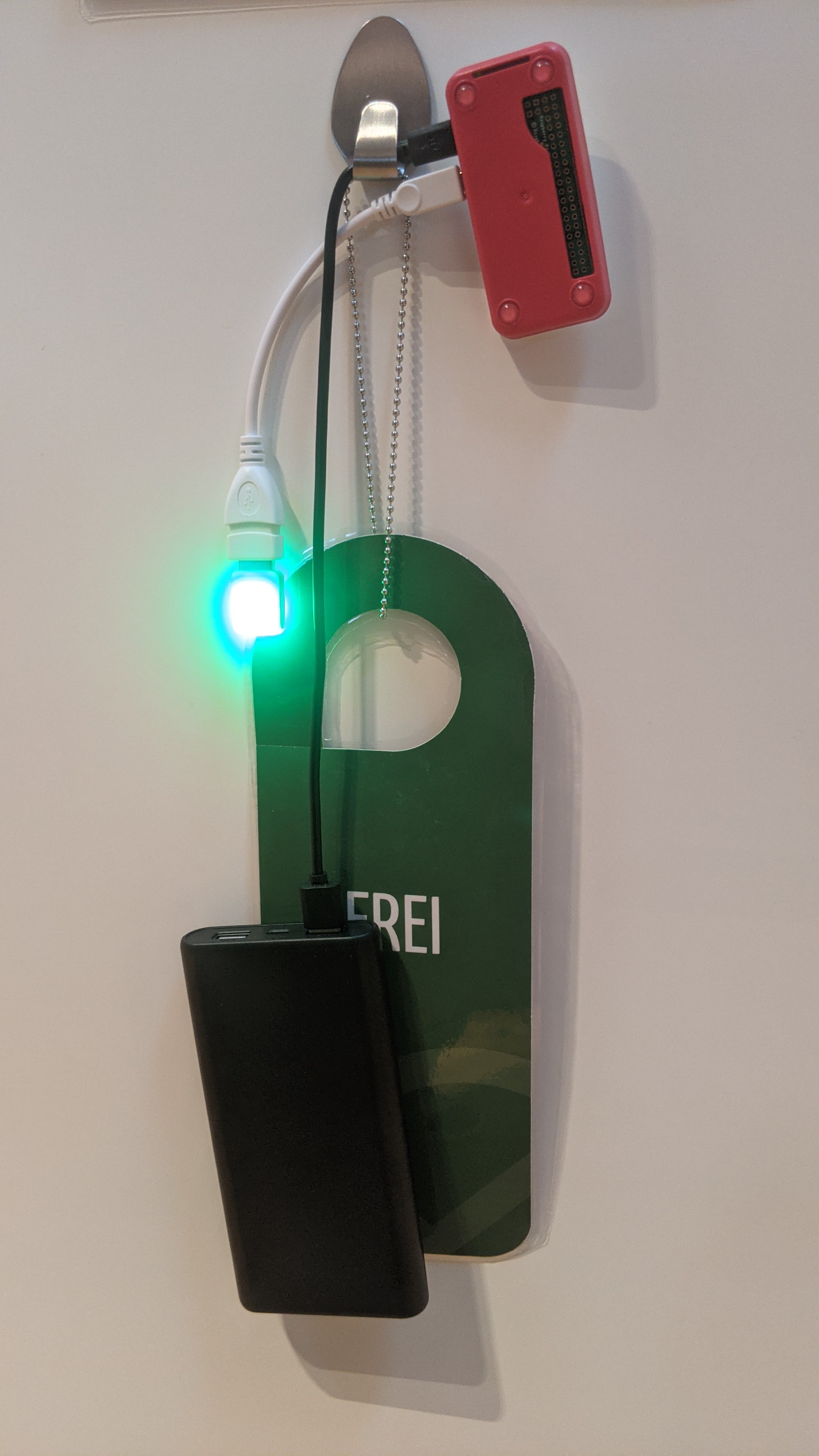
The following pictures show the final result: a Raspberry Pi Zero W with a connected blink(1) mk3 LED. The Pi runs a small Go program that establishes the MQTT connection and then toggles the LED between red and green depending on the occupancy data sent by the backend. Finally, you do not have to manually turn the sign anymore!
Of course, there is the initial investment for the hardware. The prices for the sensors vary quite significantly, somewhere between 60 and 180 Euro. But this is a one-time investment. The cloud costs are much much cheaper than this. In an average month the costs are somewhere in the range of 10 Euro cent!